
- Каталог оборудования Siemens
- Каталог продуктов Siemens Industry
- Приводная техника
- Техника автоматизации
- Системы автоматизации
- Системы визуализации SIMATIC HMI
- Системы идентификации
- Промышленные коммуникации SIMATIC NET
- Промышленные аппараты управления SIRIUS
- Промышленные информационные технологии
- Управление на базе РС
- Системы управления процессом
- Контрольно-измерительные приборы
- Анализаторы процесса
- Блоки питания SITOP
- Продукты для специальных требований
- Модули с расширенным температурным диапазоном SIPLUS
- Промышленные системы автоматизации SIMATIC
- Программируемые контроллеры
- Распределенная периферия SIMATIC ET200
- SIPLUS ET 200 systems for the control cabinet
- SIPLUS ET 200SP
- Интерфейсные модули SIPLUS
- SIPLUS extreme RAIL interface modules
- Модули ввода-вывода SIPLUS
- Модули ввода дискретных сигналов SIPLUS
- Модули вывода дискретных сигналов SIPLUS
- Модули ввода аналоговых сигналов SIPLUS
- Модули вывода аналоговых сигналов SIPLUS
- SIPLUS technology modules
- SIPLUS Communication
- SIPLUS F модули
- SIPLUS extreme RAIL digital input modules
- SIPLUS extreme RAIL digital output modules
- SIPLUS extreme RAIL analog input modules
- SIPLUS extreme RAIL analog output modules
- SIPLUS extreme RAIL Communication modules
- Базовые блоки SIPLUS
- SIPLUS BusAdapter
- SIPLUS extreme RAIL BaseUnits
- SIPLUS extreme RAIL BusAdapter
- SIPLUS ET 200S
- SIPLUS ET 200MP
- ET 200M
- SIPLUS ET 200SP
- Компоненты SIPLUS PROFIBUS для ET 200
- SIPLUS ET 200 systems for the control cabinet
- Система управления перемещением SIMOTION
- Распределенные системы управления
- Системы оперативного управления и мониторинга
- Промышленные коммуникации
- Аппаратура управления
- Блоки питания
- Дополнения SIPLUS
- Промышленные системы автоматизации SIMATIC
- Системы телеметрии
- IO Systems for heating units
- Automatic door controls
- Condition monitoring systems
- Time synchronization
- Модули с расширенным температурным диапазоном SIPLUS
- Energy
- Автоматизация и безопасность зданий
- Низковольтная коммутационная техника
- Технология безопасности
- Системные решения и продукты для отраслей
- Сервис
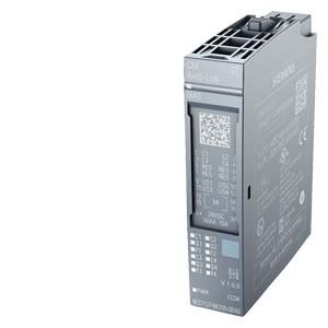
SIPLUS extreme RAIL CM 4x IO-Link
- Заказные данные (1)
- Аксессуары (4)
- Информационные материалы
Информационные материалы
- SIPLUS ET 200SP CM 4XIO-LINK ST T1 RAIL communication module:
Serial communication module for connecting up to 4 IO-Link devices in accordance with IO-Link specification V1.0 and V1.1. The IO-Link parameters are configured using the Port Configuration Tool (PCT), version V3.0 and higher. - Approved in accordance with the EN 50155, EN 15121, EN 50124, EN 50125 and EN 45545 railway standards for use in rail traffic
- Time-based IO
Time-based IO ensures that signals are output with a precisely defined response time. By combining inputs and outputs, for example, passing products can be accurately measured or fluids dosed in precise quantities. - Supported data transfer rates
- COM1 (4.8 kbit/s)
- COM2 (38.4 kbit/s)
- COM3 (230.4 kbit/s)
- Expansion limits
- Length of cable: Max. 20 m
- Max. 32 bytes of input and output data per port
- Max. 144 bytes of input data and 128 bytes of output data per module
- Supported ET 200SP system functions
- Replacement without PG with automatic backup without the engineering tool of the IO Link Device Parameter (V1.1 devices only) and the IO-Link master parameters by means of redundant saving of parameters on the e-coding element
- Reparameterization during operation
- Identification data I&M
- Firmware update
- PROFIenergy
- Can be plugged into Type A0 BaseUnits (BU) with automatic e-coding
- LED indicators
- DIAG: Operating state indicator (green/red) of the module
- C1..C4: Port status indicator (green) for Port 1, 2, 3 and 4
- Q1..Q4: Channel status indicator (green) for Port 1, 2, 3 and 4
- F1..F4: Port fault indicator (red) for Port 1, 2, 3 and 4
- PWR: Supply voltage indicator (green)
- Clear labeling on front of module
- Plain text identification of the module type and function class
- 2D matrix code (order and serial number)
- Connection diagram
- Color-coding of the module class CM: Silver
- Hardware and firmware version
- Complete Article No.
- Optional accessories
- Labeling strips
- Equipment labeling plate
- Color-coding plate with color code CC04
- Optional system-integrated shield connection
Overview of CM 4xIO-Link
Communication module
Article No.
CC-Code
BU type
PU
CM 4xIO-Link
6AG2137-6BD00-1BA0
CC04
A0
1
Overview of BaseUnits
BaseUnit
Article No.
CC-Codes for process terminals
CC-Codes for AUX terminals
PU
BU type A0
- New load group (light)
- 16 process terminals
- With 10 AUX terminals
6AG2193-6BP20-4DA0
CC01 to CC05
CC71 to CC73
1
BU type A0
- New load group (light)
- 16 process terminals
- Without AUX terminals
6AG2193-6BP00-4DA0
CC01 to CC05
--
1
BU type A0
- Forwarding of load group (dark)
- 16 process terminals
- With 10 AUX terminals
6AG2193-6BP20-4BA0
CC01 to CC05
CC71 to CC73
1
BU type A0
- Forwarding of load group (dark)
- 16 process terminals
- Without AUX terminals
6AG2193-6BP00-4BA0
CC01 to CC05
--
1
Область применения
- The SIPLUS ET 200SP CM 4XIO-LINK ST T1 RAIL communication module enables data exchange with up to 4 external IO Link devices via one 3-wire cable each.
- Comprehensive parameterization options make it possible to adapt the controller flexibly to the communication partner.
- Thanks to the compatibility of IO-Link with standard sensors, commercially available sensors in accordance with IEC 61131 Type 1 can also be operated on the IO-Link master.
Дизайн
Usable BaseUnits (BU)
All BUs of type A0 are available for the SIPLUS ET 200SP CM 4XIO-LINK ST T1 RAIL communication module.
Load group formation
A light-colored BU separates the self-assembling, internal voltage buses (P1, P2, AUX) and thus opens a new load group. The supply voltage of a load group must be fed in at the light BU of this load group.
A dark BU forwards the supply voltage of the adjacent light BU on the left via the self-assembling voltage buses P1, P2 and AUX. A new infeed is therefore only required on the next light BU to the right. The setting of a further light BU is required whenever
- a new load group is to be formed (for example, for isolating the supply voltage from module groups) or
- the maximum current simultaneously required by the load group exceeds the permissible limit of 10 A.
Color identification of the terminals
The potentials at the terminals of the BaseUnit are defined by the inserted I/O module in each case. To prevent wiring faults, the potentials of the terminals can optionally be identified by means of module-specific color-coded labels. The color-coded label that matches the respective I/O module is defined by the color code CCxx of the I/O module. This color code is also printed on the front of the module.
For the communications module "CM 4x IO‑Link", the color-coding label with the color code CC04 is to be used.
In BaseUnits with the additional ten internally jumpered AUX terminals, these can also be identified with color-coded labels. For the ten AUX terminals, color-coded labels are available in red, blue, and yellow/green.
Labeling
Labeling strips
Labeling strips can be inserted on the front of the interface modules or I/O modules and individually labeled via STEP 7, macros, etc. No special additional holder is required. If required, they can be easily replaced with the component.
Equipment labeling plates
Equipment labeling plates enable the equipment to be easily identified (e.g. compliant with EN 81346). They are easily plugged onto the required component (interface modules, I/O modules and BaseUnits) and when required, they can be easily replaced with the component.
The following labeling components are available:
- Film labeling strips, light-gray, roll with 500 strips, perforated, for thermal transfer printers
- Film labeling strips, yellow, roll with 500 strips, perforated, for thermal transfer printers
- Card labeling strips (180 g/m2), light gray, DIN A4 sheets with 100 strips each, perforated, for laser printer
- Card labeling strips (180 g/m2), yellow, DIN A4 sheets with 100 strips each, perforated, for laser printer
- Equipment labeling plates, white, ten sheets each with 16 labels, for thermal transfer card printers or labels
System-integrated shield connection
For the space-saving and EMC-optimized connection of cable shields, a shield connection is available that is quick and easy to mount. This consists of one shield connection element that can be plugged onto the BaseUnit and one shield terminal for each module. The low-impedance connection to the functional ground (DIN rail) is achieved without any additional wiring by the user.
Технические данные
Order number
6AG2137-6BD00-1BA0
SIPLUS ET 200SP CM 4XIO-LINK ST T1 RAIL
General information
Product type designation
ET 200SP, CM 4xIO-Link
Product function
● I&M data
Yes
Supply voltage
Rated value (DC)
24 V
Reverse polarity protection
Yes
Input current
Current consumption, max.
45 mA; without load
Encoder supply
Number of outputs
4
Output current
● Rated value
200 mA
Power loss
Power loss, typ.
1 W
Isochronous mode
Equidistance
Yes
Interrupts/diagnostics/status information
Diagnostics function
Yes
Alarms
● Diagnostic alarm
Yes; The port diagnosis is available in the IO-Link mode only.
Diagnostic messages
● Monitoring the supply voltage
Yes
Diagnostics indication LED
● Monitoring of the supply voltage (PWR-LED)
Yes; green PWR LED
● Channel status display
Yes; one green LED for channel status Qn (SIO mode) and port status Cn (IO-Link mode) per channel
● for channel diagnostics
Yes; red Fn LED
● for module diagnostics
Yes; green/red DIAG LED
Potential separation
Potential separation channels
● between the channels
No
● between the channels and backplane bus
Yes
Isolation
Isolation tested with
707 V DC (type test) and according to EN 50155 (routine test)
Standards, approvals, certificates
Railway application
● EN 50121-3-2
Yes; EMC for rail vehicles
● EN 50121-4
Yes; EMC for signal and telecommunications systems
● EN 50124-1
Yes; Railway applications - overvoltage category OV2; pollution degree PD2; rated surge voltage UNi = 0.5 kV; UNm = 24 V DC
● EN 50125-1
Yes; Rail vehicles - see ambient conditions
● EN 50125-2
Yes; Stationary electrical equipment - see ambient conditions
● EN 50125-3
Yes; Signal and telecommunications systems - see ambient conditions; vibrations and shocks: Application point outside of tracks (1 m to 3 m away from track)
● EN 50155
Yes; Rail vehicles - temperature class T1, horizontal mounting position, salt spray Class ST2
● EN 61373
Yes; Rail vehicles - vibrations and shocks: Category 1 Class A/B
● Fire protection acc. to EN 45545-2
Yes; Rail vehicles - verification on request
Ambient conditions
Ambient temperature during operation
● horizontal installation, min.
-40 °C; = Tmin; Startup @ -25 °C
● horizontal installation, max.
60 °C; = Tmax; +70 °C for 10 min (T1 acc. to EN 50155)
Extended ambient conditions
● relative to ambient temperature-atmospheric pressure-installation altitude
Tmin ... Tmax at 1080 hPa ... 795 hPa (-1000 m ... +2000 m)
Relative humidity
— With condensation, tested in accordance with IEC 60068-2-38, max.
100 %; RH incl. condensation/frost (no commissioning under condensation conditions)
Resistance
— against biologically active substances / conformity with EN 60721-3-3
Yes; Class 3B2 mold, fungus and dry rot spores (with the exception of fauna). The supplied connector covers must remain on the unused interfaces during operation!
— against biologically active substances/conformity with EN 60721-3-5
Yes; Class 5B2 mold and fungal spores (excluding fauna). The supplied plug covers must remain in place over the unused interfaces during operation!
— against chemically active substances / conformity with EN 60721-3-3
Yes; Class 3C4 (RH < 75%) incl. salt spray according to EN 60068-2-52 (degree of severity 3). The supplied connector covers must remain on the unused interfaces during operation!
— against chemically active substances/conformity with EN 60721-3-5
Yes; Class 5C3 (RH < 75%) including salt spray according to EN 50155 (ST2). The supplied plug covers must remain in place over the unused interfaces during operation!
— against mechanically active substances / conformity with EN 60721-3-3
Yes; Class 3S4 incl. sand, dust. The supplied connector covers must remain on the unused interfaces during operation!
— against mechanically active substances/conformity with EN 60721-3-5
Yes; Class 5S3 including sand and dust. The supplied plug covers must remain in place over the unused interfaces during operation!
Dimensions
Width
15 mm
Weights
Weight, approx.
30 g
Other
Note:
For use in railway applications, also observe the product information "SIPLUS extreme RAIL" A5E37661960A Online Support article 109736776
- SIPLUS ET 200SP CM 4XIO-LINK ST T1 RAIL communication module: