
- Каталог оборудования Siemens
- Каталог продуктов Siemens Industry
- Приводная техника
- Техника автоматизации
- Системы автоматизации
- Системы визуализации SIMATIC HMI
- Системы идентификации
- Промышленные коммуникации SIMATIC NET
- Промышленные аппараты управления SIRIUS
- Промышленные информационные технологии
- Управление на базе РС
- Системы управления процессом
- Контрольно-измерительные приборы
- Анализаторы процесса
- Блоки питания SITOP
- Продукты для специальных требований
- Модули с расширенным температурным диапазоном SIPLUS
- Промышленные системы автоматизации SIMATIC
- Система управления перемещением SIMOTION
- Распределенные системы управления
- Системы оперативного управления и мониторинга
- Промышленные коммуникации
- Аппаратура управления
- Блоки питания
- Дополнения SIPLUS
- Системы телеметрии
- IO Systems for heating units
- Automatic door controls
- Condition monitoring systems
- Time synchronization
- Модули с расширенным температурным диапазоном SIPLUS
- Energy
- Автоматизация и безопасность зданий
- Низковольтная коммутационная техника
- Технология безопасности
- Системные решения и продукты для отраслей
- Сервис
SIPLUS extreme RAIL BaseUnits
- Заказные данные (5)
- Информационные материалы
Информационные материалы
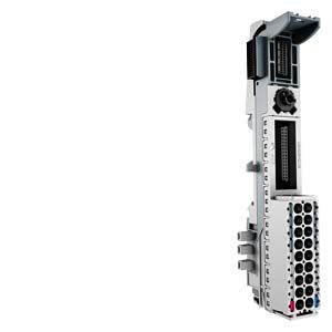
With the BaseUnits (BUs), the SIPLUS extreme RAIL ET 200SP offers a rugged and service-friendly design with permanent wiring:
- Approved in accordance with the railway standards EN 50155, EN 15121, EN 50124, EN 50125 and EN 45545 for use in rail traffic
- No tools needed for one-handed wiring using push-in terminals
- Actuation of the spring NC contacts with a standard screwdriver, with a blade width up to 3.5 mm
- Outstanding access due to arrangement of measuring tap, spring NC contacts and cable entry in columns, while at the same time reducing the space required by 64%
- Fault-proof color coding of the spring NC contacts for better orientation in the terminal panel
- Replacement of I/O modules during operation without affecting the wiring
- Operation with module gaps (gaps without I/O module)
- Automatic coding of the I/O modules prevents destruction of the electronics if a module is accidentally inserted in the wrong slot during replacement
- High EMC interference immunity:
- Self-assembling shielded backplane bus
- multi-layer conductor plate with shield levels for interference-free signal transmission from the terminal to the I/O module,
- System-integrated, space-saving shield connection for quick installation
- Self-assembling potential groups without external wiring or jumpers
- Replaceable terminal box
- Side-by-side latching of the BUs for high mechanical and EMC loads
- Optional module-specific color identification of the terminals according to the color code CC
- Optional equipment marking using slide-in equipment labeling plates
Дизайн
The different BaseUnits (BU) facilitate the exact adaptation to the required type of wiring. This enables users to select economical connection systems for the I/O modules used for their task. The TIA Selection Tool assists in the selection of the BaseUnits most suitable for the application.
BaseUnits with the following functions are available:
- Single-conductor connection, with direct connection of the shared return conductor
- Direct multi-conductor connection (2, 3 or 4-wire connection)
- Recording of the terminal temperature for the internal temperature compensation for thermocouple measurements
- AUX or additional terminals for individual use as voltage distribution terminal
The BaseUnits (BU) can be plugged onto DIN mounting rails compliant with EN 60715 (35 x 7.5 mm or 35 mm x 15 mm). The BUs are arranged next to one another beside the interface module, thereby safeguarding the electromechanical link between the individual system components. An I/O module is plugged onto the BUs, which ultimately determines the function of the respective slot and the potentials of the terminals.
Load group formation
Scalable I/O systems usually offer the possibility of individual load group formation. In the case of distributed I/O devices, this previously required an additional power module (feed module) that provided the separation from the left-hand load group as well as the infeed, display, monitoring, and diagnostics of the load voltage. It also featured a filter function against external interference and offered protection against polarity reversal.
All of these functions are now integrated into the basic components of the system in the ET 200SP. For users, this means the elimination of the power module. This saves an additional slot for each load group, resulting in greater flexibility in terms of configuration and ultimately, a saving of storage space.
A light-colored BU separates the self-assembling, internal voltage buses (P1, P2, AUX) and thus opens a new load group. The power supply of a load group must be fed in at the light BU of this load group.
A dark BU forwards the power supply of the adjacent light BU on the left via the self-assembling voltage buses P1, P2 and AUX. A new infeed is therefore only required on the next light BU to the right. The setting of a further light BU is required whenever
- a new load group is to be formed (for example, for isolating the supply voltage from module groups) or
- the maximum current simultaneously required by the load group exceeds the permissible limit of 10 A.
Labeling
Equipment labeling plates
Equipment labeling plates enable the equipment to be easily identified (e.g. compliant with EN 81346). They are easily plugged onto the required component (interface modules, I/O modules and BaseUnits) and when required, they can be easily replaced with the component.
The following labeling components are available:
- Equipment labeling plates, white, ten sheets each with 16 labels, for thermal transfer card printers or labels
Color identification of the terminals
The potentials at the terminals of the BaseUnit are defined by the I/O module. Optionally, the potentials of the terminals can be identified by module-specific color-coded labels to prevent wiring errors. The color-coded label that matches the respective I/O module is defined by the color code CCxx of the I/O module. This color code is also printed on the front of the module.
In BaseUnits with 10 internally jumpered AUX terminals, these can also be identified with color-coded labels. For the 10 AUX terminals, color-coded labels are available in red, blue, and yellow/green.
System-integrated shielded connection
For the space-saving and EMC-optimized connection of cable shields, a shield connection is available that is quick and easy to mount. This consists of one shield connection element that can be plugged onto the BaseUnit and one shield terminal for each module. The low-impedance connection to the functional ground (DIN rail) is achieved without any additional wiring by the user.
The BaseUnits can be equipped with an equipment labeling plate.
Технические данные
Order number
6AG2193-6BP00-4BA0
6AG2193-6BP00-4DA0
6AG2193-6BP20-4BA0
6AG2193-6BP20-4DA0
SIPLUS ET 200SP BU15-P16+A0+2B TX RAIL
SIPLUS ET 200SP BU15-P16+A0+2D TX RAIL
SIPLUS ET 200SP BU15-P16+A10+2B TX RAIL
SIPLUS ET 200SP BU15-P16+A10+2D TX RAIL
General information
Product type designation
BU Type A0, BU15-P16+A0+2B, PU 1
BU Type A0, BU15-P16+A0+2D, PU 1
BU Type A0, BU15-P16+A10+2B, PU 1
BU Type A0, BU15-P16+A10+2D, PU 1
Standards, approvals, certificates
Railway application
● EN 50121-3-2
Yes; EMC for rail vehicles
Yes; EMC for rail vehicles
Yes; EMC for rail vehicles
Yes; EMC for rail vehicles
● EN 50121-4
Yes; EMC for signal and telecommunications systems
Yes; EMC for signal and telecommunications systems
Yes; EMC for signal and telecommunications systems
Yes; EMC for signal and telecommunications systems
● EN 50124-1
Yes; Railway applications - overvoltage category OV2; pollution degree PD2; rated surge voltage UNi = 0.5 kV; UNm = 24 V DC
Yes; Railway applications - overvoltage category OV2; pollution degree PD2; rated surge voltage UNi = 0.5 kV; UNm = 24 V DC
Yes; Railway applications - overvoltage category OV2; pollution degree PD2; rated surge voltage UNi = 0.5 kV; UNm = 24 V DC
Yes; Railway applications - overvoltage category OV2; pollution degree PD2; rated surge voltage UNi = 0.5 kV; UNm = 24 V DC
● EN 50125-1
Yes; Rail vehicles - see ambient conditions
Yes; Rail vehicles - see ambient conditions
Yes; Rail vehicles - see ambient conditions
Yes; Rail vehicles - see ambient conditions
● EN 50125-2
Yes; Stationary electrical equipment - see ambient conditions
Yes; Stationary electrical equipment - see ambient conditions
Yes; Stationary electrical equipment - see ambient conditions
Yes; Stationary electrical equipment - see ambient conditions
● EN 50125-3
Yes; Signal and telecommunications systems - see ambient conditions; vibrations and shocks: Application point outside of tracks (1 m to 3 m away from track)
Yes; Signal and telecommunications systems - see ambient conditions; vibrations and shocks: Application point outside of tracks (1 m to 3 m away from track)
Yes; Signal and telecommunications systems - see ambient conditions; vibrations and shocks: Application point outside of tracks (1 m to 3 m away from track)
Yes; Signal and telecommunications systems - see ambient conditions; vibrations and shocks: Application point outside of tracks (1 m to 3 m away from track)
● EN 50155
Yes; Rail vehicles - temperature class Tx, horizontal mounting position, salt spray Class ST2
Yes; Rail vehicles - temperature class Tx, horizontal mounting position, salt spray Class ST2
Yes; Rail vehicles - temperature class Tx, horizontal mounting position, salt spray Class ST2
Yes; Rail vehicles - temperature class Tx, horizontal mounting position, salt spray Class ST2
● EN 61373
Yes; Rail vehicles - vibrations and shocks: Category 1 Class A/B
Yes; Rail vehicles - vibrations and shocks: Category 1 Class A/B
Yes; Rail vehicles - vibrations and shocks: Category 1 Class A/B
Yes; Rail vehicles - vibrations and shocks: Category 1 Class A/B
● Fire protection acc. to EN 45545-2
Yes; Rail vehicles - verification on request
Yes; Rail vehicles - verification on request
Yes; Rail vehicles - verification on request
Yes; Rail vehicles - verification on request
Ambient conditions
Ambient temperature during operation
● horizontal installation, min.
-40 °C; = Tmin
-40 °C; = Tmin
-40 °C; = Tmin
-40 °C; = Tmin
● horizontal installation, max.
70 °C; = Tmax; +85 °C for 10 min (Tx acc. to EN 50155)
70 °C; = Tmax; +85 °C for 10 min (Tx acc. to EN 50155)
70 °C; = Tmax; +85 °C for 10 min (Tx acc. to EN 50155)
70 °C; = Tmax; +85 °C for 10 min (Tx acc. to EN 50155)
Extended ambient conditions
● relative to ambient temperature-atmospheric pressure-installation altitude
Tmin ... Tmax at 1080 hPa ... 795 hPa (-1000 m ... +2000 m)
Tmin ... Tmax at 1080 hPa ... 795 hPa (-1000 m ... +2000 m)
Tmin ... Tmax at 1080 hPa ... 795 hPa (-1000 m ... +2000 m)
Tmin ... Tmax at 1080 hPa ... 795 hPa (-1000 m ... +2000 m)
Relative humidity
— With condensation, tested in accordance with IEC 60068-2-38, max.
100 %; RH incl. condensation/frost (no commissioning under condensation conditions)
100 %; RH incl. condensation/frost (no commissioning under condensation conditions)
100 %; RH incl. condensation/frost (no commissioning under condensation conditions)
100 %; RH incl. condensation/frost (no commissioning under condensation conditions)
Resistance
— against biologically active substances / conformity with EN 60721-3-3
Yes; Class 3B2 mold, fungus and dry rot spores (with the exception of fauna). The supplied connector covers must remain on the unused interfaces during operation!
Yes; Class 3B2 mold, fungus and dry rot spores (with the exception of fauna). The supplied connector covers must remain on the unused interfaces during operation!
Yes; Class 3B2 mold, fungus and dry rot spores (with the exception of fauna). The supplied connector covers must remain on the unused interfaces during operation!
Yes; Class 3B2 mold, fungus and dry rot spores (with the exception of fauna). The supplied connector covers must remain on the unused interfaces during operation!
— against biologically active substances/conformity with EN 60721-3-5
Yes; Class 5B2 mold and fungal spores (excluding fauna). The supplied plug covers must remain in place over the unused interfaces during operation!
Yes; Class 5B2 mold and fungal spores (excluding fauna). The supplied plug covers must remain in place over the unused interfaces during operation!
Yes; Class 5B2 mold and fungal spores (excluding fauna). The supplied plug covers must remain in place over the unused interfaces during operation!
Yes; Class 5B2 mold and fungal spores (excluding fauna). The supplied plug covers must remain in place over the unused interfaces during operation!
— against chemically active substances / conformity with EN 60721-3-3
Yes; Class 3C4 (RH < 75%) incl. salt spray according to EN 60068-2-52 (degree of severity 3). The supplied connector covers must remain on the unused interfaces during operation!
Yes; Class 3C4 (RH < 75%) incl. salt spray according to EN 60068-2-52 (degree of severity 3). The supplied connector covers must remain on the unused interfaces during operation!
Yes; Class 3C4 (RH < 75%) incl. salt spray according to EN 60068-2-52 (degree of severity 3). The supplied connector covers must remain on the unused interfaces during operation!
Yes; Class 3C4 (RH < 75%) incl. salt spray according to EN 60068-2-52 (degree of severity 3). The supplied connector covers must remain on the unused interfaces during operation!
— against chemically active substances/conformity with EN 60721-3-5
Yes; Class 5C3 (RH < 75%) including salt spray according to EN 50155 (ST2). The supplied plug covers must remain in place over the unused interfaces during operation!
Yes; Class 5C3 (RH < 75%) including salt spray according to EN 50155 (ST2). The supplied plug covers must remain in place over the unused interfaces during operation!
Yes; Class 5C3 (RH < 75%) including salt spray according to EN 50155 (ST2). The supplied plug covers must remain in place over the unused interfaces during operation!
Yes; Class 5C3 (RH < 75%) including salt spray according to EN 50155 (ST2). The supplied plug covers must remain in place over the unused interfaces during operation!
— against mechanically active substances / conformity with EN 60721-3-3
Yes; Class 3S4 incl. sand, dust. The supplied connector covers must remain on the unused interfaces during operation!
Yes; Class 3S4 incl. sand, dust. The supplied connector covers must remain on the unused interfaces during operation!
Yes; Class 3S4 incl. sand, dust. The supplied connector covers must remain on the unused interfaces during operation!
Yes; Class 3S4 incl. sand, dust. The supplied connector covers must remain on the unused interfaces during operation!
— against mechanically active substances/conformity with EN 60721-3-5
Yes; Class 5S3 including sand and dust. The supplied plug covers must remain in place over the unused interfaces during operation!
Yes; Class 5S3 including sand and dust. The supplied plug covers must remain in place over the unused interfaces during operation!
Yes; Class 5S3 including sand and dust. The supplied plug covers must remain in place over the unused interfaces during operation!
Yes; Class 5S3 including sand and dust. The supplied plug covers must remain in place over the unused interfaces during operation!
Dimensions
Width
15 mm
15 mm
15 mm
15 mm
Height
117 mm
117 mm
141 mm
141 mm
Weights
Weight, approx.
40 g
40 g
50 g
50 g
Other
Note:
For use in railway applications, also observe the product information "SIPLUS extreme RAIL" A5E37661960A Online Support article 109736776
For use in railway applications, also observe the product information "SIPLUS extreme RAIL" A5E37661960A Online Support article 109736776
For use in railway applications, also observe the product information "SIPLUS extreme RAIL" A5E37661960A Online Support article 109736776
For use in railway applications, also observe the product information "SIPLUS extreme RAIL" A5E37661960A Online Support article 109736776
Order number
6AG2193-6BP00-4BD0
SIPLUS ET 200SP BU20-P12+A0+0B TX RAIL
General information
Product type designation
BU20-P12+A0+0B
Standards, approvals, certificates
Railway application
● EN 50121-3-2
Yes; EMC for rail vehicles
● EN 50121-4
Yes; EMC for signal and telecommunications systems
● EN 50124-1
Yes; Railway applications - overvoltage category OV2; pollution degree PD2; rated surge voltage UNi = 0.5 kV; UNm = 24 V DC
● EN 50125-1
Yes; Rail vehicles - see ambient conditions
● EN 50125-2
Yes; Stationary electrical equipment - see ambient conditions
● EN 50125-3
Yes; Signal and telecommunications systems - see ambient conditions; vibrations and shocks: Application point outside of tracks (1 m to 3 m away from track)
● EN 50155
Yes; Rail vehicles - temperature class Tx, horizontal mounting position, salt spray Class ST2
● EN 61373
Yes; Rail vehicles - vibrations and shocks: Category 1 Class A/B
● Fire protection acc. to EN 45545-2
Yes; Rail vehicles - verification on request
Ambient conditions
Ambient temperature during operation
● horizontal installation, min.
-40 °C; = Tmin
● horizontal installation, max.
70 °C; = Tmax; +85 °C for 10 min (Tx acc. to EN 50155)
Extended ambient conditions
● relative to ambient temperature-atmospheric pressure-installation altitude
Tmin ... Tmax at 1080 hPa ... 795 hPa (-1000 m ... +2000 m)
Relative humidity
— With condensation, tested in accordance with IEC 60068-2-38, max.
100 %; RH incl. condensation/frost (no commissioning under condensation conditions)
Resistance
— against biologically active substances / conformity with EN 60721-3-3
Yes; Class 3B2 mold, fungus and dry rot spores (with the exception of fauna). The supplied connector covers must remain on the unused interfaces during operation!
— against biologically active substances/conformity with EN 60721-3-5
Yes; Class 5B2 mold and fungal spores (excluding fauna). The supplied plug covers must remain in place over the unused interfaces during operation!
— against chemically active substances / conformity with EN 60721-3-3
Yes; Class 3C4 (RH < 75%) incl. salt spray according to EN 60068-2-52 (degree of severity 3). The supplied connector covers must remain on the unused interfaces during operation!
— against chemically active substances/conformity with EN 60721-3-5
Yes; Class 5C3 (RH < 75%) including salt spray according to EN 50155 (ST2). The supplied plug covers must remain in place over the unused interfaces during operation!
— against mechanically active substances / conformity with EN 60721-3-3
Yes; Class 3S4 incl. sand, dust. The supplied connector covers must remain on the unused interfaces during operation!
— against mechanically active substances/conformity with EN 60721-3-5
Yes; Class 5S3 including sand and dust. The supplied plug covers must remain in place over the unused interfaces during operation!
Dimensions
Width
20 mm
Height
117 mm
Weights
Weight, approx.
47 g
Other
Note:
For use in railway applications, also observe the product information "SIPLUS extreme RAIL" A5E37661960A Online Support article 109736776