
- Каталог оборудования Siemens
- Каталог продуктов Siemens Industry
- Приводная техника
- Техника автоматизации
- Системы автоматизации
- Промышленные системы автоматизации SIMATIC
- Программируемые контроллеры
- Распределенный ввод/вывод
- Станции ET 200 для установки в шкафы управления
- Станции ET 200 для установки вне шкафов управления
- ET 200pro
- Интерфейсные модули
- Модули центральных процессоров
- Модули ввода/ вывода
- SITOP PSU300P/SIMATIC ET200pro со степенью защиты IP67
- Фидеры нагрузки для ET 200pro
- Решения для фидеров нагрузки ET 200pro/ PROFIsafe
- Аксессуары для силовых модулей ET 200pro
- ET 200pro FC Frequency Converter
- ПО для ET 200pro
- Дополнительные продукты для ET 200pro
- ET 200AL
- ET 200eco PN
- Модуль ведущего устройства IO-Link ET 200eco PN
- ET 200eco
- ET 200R
- ET 200pro
- IO Systems for heating units
- Технологические компоненты для PROFIBUS
- Технологические компоненты PROFINET
- Сетевые компоненты для PROFIBUS
- Межсетевые переходы
- Система автоматизации SIMATIC TDC
- Программное обеспечение для SIMATIC S7/WinAC
- Программаторы
- SIEMENS Solution Partner
- Test
- Motion Control - система SIMOTION
- Системы автоматизации на базе СЧПУ SINUMERIK
- Система соединителей/ шкафы управления
- Программное обеспечение для систем автоматизации
- Промышленные системы автоматизации SIMATIC
- Системы визуализации SIMATIC HMI
- Системы идентификации
- Промышленные коммуникации SIMATIC NET
- Промышленные аппараты управления SIRIUS
- Промышленные информационные технологии
- Управление на базе РС
- Системы управления процессом
- Контрольно-измерительные приборы
- Анализаторы процесса
- Блоки питания SITOP
- Продукты для специальных требований
- Системы автоматизации
- Energy
- Автоматизация и безопасность зданий
- Низковольтная коммутационная техника
- Технология безопасности
- Системные решения и продукты для отраслей
- Сервис
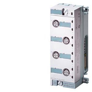
Аналоговые модули расширения EM 144, EM 145
- Заказные данные (6)
- Аксессуары (4)
- Информационные материалы
Информационные материалы
- Модули расширения для подключения аналоговых датчиков и исполнительных устройств.
- С поддержкой диагностических функций, контролем граничных значений параметров и возможностью перевода каналов в заданные состояния при остановке центрального процессора.
Область применения
Модули расширения для подключения к станции ET 200pro аналоговых датчиков и исполнительных устройств.
Состав модулей ввода аналоговых сигналов:
- 4 AI-U, ±10 В; ±5 В; 0 ... 10 В; 1 ... 5 В.
- 4 AI-I, ±20 мА; 0 ... 20 мА; 4 ... 20 мА.
Состав модулей вывода аналоговых сигналов (в подготовке):
- 4 AO-U, ±10 В; 0 ... 10 В; 1 ... 5 В.
- 4 AO-I, ±20 мА; 0 ... 20 мА; 4 ... 20 мА.
Соединительный модуль для аналоговых модулей расширения (должен заказываться отдельно):
- CM IO 4x M12
Дизайн
Датчики и исполнительные устройства модключаются через 5-полюсные гнезда M12 соединительного модуля.
Назначение контактов
Контакт
Назначение
Гнездо M12 соединительного модуля CM IO 4 x M12
AI-U
AI-I
1
Питание электроники/ датчика (1L+)
Питание электроники/ датчика (1L+)
Смотри следующий рисунок
2
Входной сигнал "+"
Входной сигнал "+"
3
Масса цепи питания электроники/ датчика (1M)
Масса цепи питания электроники/ датчика (1M)
4
Входной сигнал "-"
Входной сигнал "-"
5
Земля
Земля
S
Земля
Земля
Контакт
Назначение
Гнездо M12 соединительного модуля CM IO 4 x M12
AO-U
AO-I
1
Питание электроники/ нагрузки (1L+)
Питание электроники/ нагрузки (1L+)
Смотри следующий рисунок
2
Выходной сигнал "+"
Выходной сигнал "+"
3
Масса цепи питания электроники/ нагрузки (1M)
Масса цепи питания электроники/ нагрузки (1M)
4
Выходной сигнал "-"
Выходной сигнал "-"
5
Земля
Земля
S
Земля
Земля
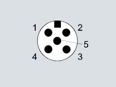
Замечание: “S” - контакт на корпусе соединителя.
Функции
Модули ввода выполняют аналого-цифровое преобразование входных сигналов станции ET 200pro и формируют цифровые значения, используемые центральным процессором ведущего устройства в ходе выполнения программы. Модули вывода выполняют цифро-аналоговое преобразование сформированных центральным процессором цифровых величин и формируют выходные аналоговые сигналы станции ET 200pro.
Технические данные
Order number
6ES7144-4FF01-0AB0
6ES7144-4GF01-0AB0
6ES7144-4JF00-0AB0
6ES7144-4PF00-0AB0
ET200PRO, EM 4AI-U HF
ET200PRO, EM 4AI-I HF
ET200PRO, EM 4 AI-RTD HF
ET200PRO, EM 4 AI-TC HF
Supply voltage
Rated value (DC)
24 V
24 V
24 V
24 V
Reverse polarity protection
Yes; against destruction
Yes; against destruction
Yes; against destruction
Yes; against destruction
Input current
from supply voltage 1L+, max.
40 mA; Typical
40 mA; Typical
27 mA; Typical
34 mA; Typical
from backplane bus 3.3 V DC, max.
12 mA; Typical
12 mA; Typical
10 mA; Typical
20 mA; Typical
Encoder supply
Number of outputs
4
4
Short-circuit protection
Yes; per module, electronic to frame
Yes; per module, electronic to frame
Output current
● up to 55 °C, max.
1 A
1 A
Power loss
Power loss, typ.
1.1 W
1.1 W
0.7 W
0.7 W
Address area
Address space per module
● Address space per module, max.
8 byte
8 byte
8 byte
8 byte
Analog inputs
Number of analog inputs
4
4
4
4
permissible input voltage for voltage input (destruction limit), max.
35 V
20 V
permissible input current for current input (destruction limit), max.
40 mA
Constant measurement current for resistance-type transmitter, typ.
1.25 mA; 1.25 / 0.5 mA depending on measuring range
Cycle time (all channels) max.
5 ms
10 ms
83 ms; 83 ms at 50 Hz; 69 ms at 60 Hz
Number of active channels per module x basic conversion time
Technical unit for temperature measurement adjustable
Yes; Degrees Celsius/degrees Fahrenheit
Yes; °C/°F/K
Input ranges
● Voltage
Yes
No
No
Yes
● Current
No
Yes
No
No
● Thermocouple
No
No
No
Yes
● Resistance thermometer
No
No
Yes
No
● Resistance
No
No
Yes
No
Input ranges (rated values), voltages
● 0 to +10 V
Yes
● 1 V to 5 V
Yes
● -10 V to +10 V
Yes
● -5 V to +5 V
Yes
● -80 mV to +80 mV
Yes
● Input resistance (-80 mV to +80 mV)
10 MΩ
Input ranges (rated values), currents
● 0 to 20 mA
Yes
● Input resistance (0 to 20 mA)
50 Ω
● -20 mA to +20 mA
Yes
● Input resistance (-20 mA to +20 mA)
50 Ω
● 4 mA to 20 mA
Yes
● Input resistance (4 mA to 20 mA)
50 Ω
Input ranges (rated values), thermocouples
● Type B
Yes
● Input resistance (Type B)
10 MΩ
● Type E
Yes
● Input resistance (Type E)
10 MΩ
● Type J
Yes
● Input resistance (type J)
10 MΩ
● Type K
Yes
● Input resistance (Type K)
10 MΩ
● Type L
Yes
● Input resistance (Type L)
10 MΩ
● Type N
Yes
● Input resistance (Type N)
10 MΩ
● Type R
Yes
● Input resistance (Type R)
10 MΩ
● Type S
Yes
● Input resistance (Type S)
10 MΩ
● Type T
Yes
● Input resistance (Type T)
10 MΩ
Input ranges (rated values), resistance thermometer
● Cu 10
No
● Ni 100
Yes
● Input resistance (Ni 100)
10 000 kΩ
● Ni 1000
Yes
● Input resistance (Ni 1000)
10 000 kΩ
● Ni 120
Yes
● Input resistance (Ni 120)
10 000 kΩ
● Ni 200
Yes
● Input resistance (Ni 200)
10 000 kΩ
● Ni 500
Yes
● Input resistance (Ni 500)
10 000 kΩ
● Pt 100
Yes
● Input resistance (Pt 100)
10 000 kΩ
● Pt 1000
Yes
● Input resistance (Pt 1000)
10 000 kΩ
● Pt 200
Yes
● Input resistance (Pt 200)
10 000 kΩ
● Pt 500
Yes
● Input resistance (Pt 500)
10 000 kΩ
Input ranges (rated values), resistors
● 0 to 150 ohms
Yes
● Input resistance (0 to 150 ohms)
10 000 kΩ
● 0 to 300 ohms
Yes
● Input resistance (0 to 300 ohms)
10 000 kΩ
● 0 to 600 ohms
Yes
● Input resistance (0 to 600 ohms)
10 000 kΩ
● 0 to 3000 ohms
Yes
● Input resistance (0 to 3000 ohms)
10 000 kΩ
Thermocouple (TC)
Temperature compensation
— internal temperature compensation
Yes
— external temperature compensation with compensations socket
Yes
Characteristic linearization
● parameterizable
Yes
— for resistance thermometer
Ptxxx, Nixxx
Cable length
● shielded, max.
30 m
30 m
30 m
30 m
Analog value generation for the inputs
Measurement principle
integrating
integrating
integrating
integrating
Integration and conversion time/resolution per channel
● Resolution with overrange (bit including sign), max.
15 bit; 15 bits + sign at ±10 V, at ±5 V; 15 bits at 0 V to 10 V, at 1 V to 5 V
15 bit; 15 bits + sign at ±10 V, at ±5 V; 15 bits at 0 V to 10 V, at 1 V to 5 V
15 bit; at 150, 300, 600 und 3000 ohms; otherwise 15 bits + sign
15 bit; + sign
● Integration time (ms)
0,3 / 16,7 / 20 / 60
0,3 / 16,7 / 20 / 60
20 / 16,667
2,5 / 16,67 / 20 / 100 ms
● Interference voltage suppression for interference frequency f1 in Hz
16,67 / 50 / 60 / 3 600
16,67 / 50 / 60 / 3 600
50 / 60 Hz
10 / 50 / 60 / 400 Hz
● Conversion time (per channel)
1.1 ms
1.1 ms
20.625 ms; 20.625 ms at 50 Hz; 17.25 ms at 60 Hz
4.7/19/22/102 ms
Smoothing of measured values
● parameterizable
Yes
Yes
Yes
Yes
● Step: None
Yes; 1 x cycle time
Yes; 1 x cycle time
Yes; 1 x cycle time
Yes; 1 x cycle time
● Step: low
Yes; 4 x cycle time
Yes; 4 x cycle time
Yes; 4 x cycle time
Yes; 4 x cycle time
● Step: Medium
Yes; 16 x cycle time
Yes; 16 x cycle time
Yes; 16 x cycle time
Yes; 16 x cycle time
● Step: High
Yes; 64 x cycle time
Yes; 64 x cycle time
Yes; 64 x cycle time
Yes; 64 x cycle time
Encoder
Connection of signal encoders
● for voltage measurement
Yes
Yes
● for current measurement as 2-wire transducer
Yes
● for current measurement as 4-wire transducer
Yes
● for resistance measurement with two-wire connection
Yes; Line resistances are also measured
● for resistance measurement with three-wire connection
Yes
● for resistance measurement with four-wire connection
Yes
Errors/accuracies
Linearity error (relative to input range), (+/-)
0.0075 %
0.0075 %
0.05 %
0.01 %
Temperature error (relative to input range), (+/-)
0.00075 %/K
0.00075 %/K
0.002 %/K
0.0004 %/K; Positive temperature
Crosstalk between the inputs, min.
-70 dB
-70 dB
-50 dB
-90 dB; max.
Repeat accuracy in steady state at 25 °C (relative to input range), (+/-)
0.004 %
0.004 %
0.015 %
0.01 %
Operational error limit in overall temperature range
● Voltage, relative to input range, (+/-)
0.1 %
0.12 %; Positive temperature
● Current, relative to input range, (+/-)
0.1 %
● Resistance thermometer, relative to input range, (+/-)
0.175 %
Basic error limit (operational limit at 25 °C)
● Voltage, relative to input range, (+/-)
0.075 %
0.1 %
● Current, relative to input range, (+/-)
0.075 %
● Resistance thermometer, relative to input range, (+/-)
0.125 %
Interference voltage suppression for f = n x (f1 +/- 1 %), f1 = interference frequency
● Series mode interference (peak value of interference < rated value of input range), min.
50 dB
42 dB
● Common mode interference (USS < 2.5 V) , min.
70 dB; Interference voltage < 5 V
85 dB; Interference voltage < 10 V
Interference voltage suppression for f = n x (f1 +/- 0.5 %), f1 = interference frequency
● Series mode interference (peak value of interference < rated value of input range), min.
60 dB
60 dB
● Common mode interference (USS < 2.5 V) , min.
80 dB; Interference voltage < 10 V
80 dB; Interference voltage < 5 V
Interrupts/diagnostics/status information
Diagnostic functions
Yes
Yes
Yes
Yes
Alarms
● Diagnostic alarm
Yes; Parameterizable
Yes; Parameterizable
Yes; Parameterizable
Yes; Parameterizable
● Hardware interrupt
Yes; (limit value alarm), can be parameterized for channel 0
Yes; (limit value alarm), can be parameterized for channel 0
No
No
Diagnostic messages
● Diagnostic information readable
Yes
Yes
Yes
Yes
● Wire-break
Yes; at 1 to 5 V
Yes; at 4 to 20 mA
Yes
Yes
● Short-circuit
Yes; at 1 to 5 V
Yes; at 4 to 20 mA
● Overflow/underflow
Yes
Yes
Diagnostics indication LED
● Group error SF (red)
Yes
Yes
Yes
Yes
Parameter
Diagnostics wire break
Yes
Yes
Measurement type/range
R4L / R3L / R2L/ TR4L / TR3L / TR2L
Deactivated/ +/- 80 mV/ TC-EL Type T (Cu-CuNi)/ TC-EL Type K (NiCr-Ni)/ TC-EL Type B (PtRh-PtRh)/ TC-EL Type N (NiCrSi-NiSi)/ TC-EL Typ E (NiCr-CuNi)/ TC-EL Type R (PtRh-Pt)/ TC-EL Type S (PtRh-Pt)/ TC-EL Type J (Fe-Cu-Ni)/ TC-EL Type L (Fe-CuNi)
Comparison point
None/internal/RTD(0)/dyn. ref. temp./fix. ref. temp.
Potential separation
Potential separation analog inputs
● between the channels
No
No
No
No
● between the channels and backplane bus
Yes
Yes
Yes
Yes
Isolation
Isolation tested with
707 V DC (type test)
707 V DC (type test)
707 V DC (type test)
707 V DC (type test)
Dimensions
Width
45 mm
45 mm
45 mm
45 mm
Height
130 mm
130 mm
130 mm
130 mm
Depth
35 mm
35 mm
35 mm
35 mm
Weights
Weight, approx.
150 g
150 g
150 g
150 g
Order number
6ES7145-4FF00-0AB0
6ES7145-4GF00-0AB0
ET200PRO, EM 4AO-U HF
ET200PRO, EM 4 AO-I HF
Supply voltage
Rated value (DC)
24 V
24 V
Reverse polarity protection
Yes; against destruction
Yes; against destruction
Input current
from supply voltage 1L+, max.
65 mA
110 mA
from backplane bus 3.3 V DC, max.
10 mA
10 mA
Actuator supply
Number of outputs
4
4
Short-circuit protection
Yes; per module
Yes; per module
Output current
● up to 55 °C, max.
1 A
1 A
Power loss
Power loss, typ.
1.7 W
2.3 W
Address area
Address space per module
● Address space per module, max.
8 byte
8 byte
Analog outputs
Number of analog outputs
4
4
Voltage output, short-circuit protection
Yes; per channel, electronic to chassis
Yes; per module, electronic to frame
Voltage output, short-circuit current, max.
50 mA
Current output, no-load voltage, max.
16 V
Cycle time (all channels) max.
3 ms
3 ms
Output ranges, voltage
● 0 to 10 V
Yes
● 1 V to 5 V
Yes
● -10 V to +10 V
Yes
Output ranges, current
● 0 to 20 mA
Yes
● -20 mA to +20 mA
Yes
● 4 mA to 20 mA
Yes
Connection of actuators
● for voltage output two-wire connection
Yes
● for voltage output four-wire connection
Yes
● for current output two-wire connection
Yes
● for current output four-wire connection
Yes
Load impedance (in rated range of output)
● with voltage outputs, min.
1 000 Ω
● with voltage outputs, capacitive load, max.
1 µF
● with current outputs, max.
600 Ω
● with current outputs, inductive load, max.
1 mH
Destruction limits against externally applied voltages and currents
● Voltages at the outputs towards MANA
16 V; Permanent
● Current, max.
100 mA
Cable length
● shielded, max.
30 m
30 m
Analog value generation for the outputs
Integration and conversion time/resolution per channel
● Resolution with overrange (bit including sign), max.
15 bit; at -10 to +10 V; 14 bits at 1 to 5 V; 15 bits at 0 to 10 V
15 bit; at +/- 20 mA; 14 bits at 0 to 20 mA; 15 bits at 4 to 20 mA
● Conversion time (per channel)
0.7 ms
0.7 ms
Settling time
● for resistive load
0.1 ms
0.1 ms
● for capacitive load
6 ms
● for inductive load
1 ms
Errors/accuracies
Output ripple (relative to output range, bandwidth 0 to 50 kHz), (+/-)
0.02 %
0.02 %
Linearity error (relative to output range), (+/-)
0.1 %
0.1 %
Temperature error (relative to output range), (+/-)
0.01 %/K
0.01 %/K
Repeat accuracy in steady state at 25 °C (relative to output range), (+/-)
0.05 %
0.05 %
Operational error limit in overall temperature range
● Voltage, relative to output range, (+/-)
0.2 %
● Current, relative to output range, (+/-)
0.2 %
Basic error limit (operational limit at 25 °C)
● Voltage, relative to output range, (+/-)
0.15 %
● Current, relative to output range, (+/-)
0.15 %
Interrupts/diagnostics/status information
Diagnostic functions
Yes
Substitute values connectable
Yes
Yes
Alarms
● Diagnostic alarm
Yes; Parameterizable
Yes; Parameterizable
● Hardware interrupt
No
No
Diagnostic messages
● Diagnostic information readable
Yes
Yes
● Wire-break
No
Yes; per channel, not in zero range
● Short-circuit
Yes; per channel, not in zero range
No
Diagnostics indication LED
● Group error SF (red)
Yes
Yes
Parameter
Diagnostics short-circuit
Outputs; sensor supply to M
Encoder supply to M
Potential separation
Potential separation analog outputs
● between the channels
No
No
● between the channels and backplane bus
Yes
Yes
Isolation
Isolation tested with
707 V DC (type test)
707 V DC (type test)
Dimensions
Width
45 mm
45 mm
Height
130 mm
130 mm
Depth
35 mm
35 mm
Weights
Weight, approx.
150 g
150 g