
- Каталог оборудования Siemens
- Каталог продуктов Siemens Industry
- Приводная техника
- Техника автоматизации
- Energy
- Автоматизация и безопасность зданий
- Низковольтная коммутационная техника
- Технология безопасности
- Системные решения и продукты для отраслей
- Автомобильная промышленность
- Биотопливо
- Химическая промышленность
- Пищевая промышленность
- Производственные машины
- Packaging machines
- Printing presses
- Textile machines
- Converting
- Metal forming technology
- Handling systems
- Непрерывное преобразование листового материала - Converting
- Печать
- Манипуляторы
- Пластик
- Текстиль
- Обработка металлов давлением
- Упаковка
- Компоненты автоматизации для станков
- SINUMERIK 808 with SINAMICS V60/V70
- SINUMERIK 828 with SINAMICS S120
- SINUMERIK 840 with SINAMICS S120
- Introduction SINUMERIK 840D sl with SINAMICS S120
- SINUMERIK CNC control
- SINUMERIK Operate
- SINUMERIK Integrate
- SINAMICS S120 drive system
- Communication
- Engineering software
- Control Units
- Booksize format
- Chassis format
- Blocksize format
- SINAMICS S120 Combi
- SINAMICS S120M distributed servo drive
- Supplementary system components
- Encoder system connection
- Motion Control Encoder measuring systemsIncremental encodersAbsolute encodersAccessories
- Motion Control Encoder measuring systems
- CAD CREATOR
- SIMOTICS motors
- MOTION-CONNECT connection systems
- Lifecycle Services
- SINUMERIK Solution Partners
- Certificates of suitability (approvals)
- Glossary SINUMERIK 840
- Glossary SINAMICS S120 drive system
- List of abbreviations
- Приводные применения
- Горная и металлургическая промышленность
- Нефтегазовая промышленность
- Фармацевтическая промышленность
- Бумажная промышленность
- Солнечная энергетика
- Транспорт, инфраструктура, логистика
- Вода и водоподготовка
- Сбыт электроэнергии
- Возобновляемые источники энергии
- Отраслевые решения
- Отраслевые продукты
- Сервис
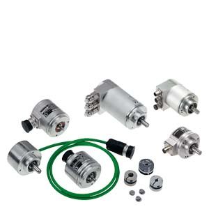
Motion Control Encoder measuring systems
- Информационные материалы
Информационные материалы
Encoder type
Interface
Safety Integrated1)
Accuracy in angular seconds
Resolution
Degree of protection
without/with
shaft inputIncremental encoders
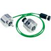
sin/cos 1 Vpp
Yes
± 18 mech. × 3600/
PPR count z2500 S/R
IP67/IP64
RS422 (TTL)
2)
± 18 mech. × 3600/
PPR count z5000 S/R
IP67/IP64
HTL
2)
± 18 mech. × 3600/
PPR count z2500 S/R
IP67/IP64
RS422 (TTL) double track
2)
Track 1: ± 63
Track 2: ± 12Track 1: 1024 S/R
Track 2: 9000 S/RIP67/IP64
Absolute encoders

DRIVE‑CLiQ
2)
± 36
Single‑turn
22 bitMulti‑turn
34 bit
(22 bit single‑turn +
12 bit multi‑turn)IP67/IP64
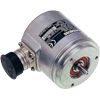
SSI
2)
± 79
(with 8192 steps)Single‑turn
13 bit (8192 steps)Multi‑turn
25 bit
(8192 steps ×
4096 revolutions)IP67/IP64
EnDat
Yes
± 60
(incremental track)Single‑turn
13 bit (8192 steps)Multi‑turn
25 bit
(8192 steps ×
4096 revolutions)IP67/IP64
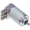
PROFIBUS DP
2)
± 79
(with 8192 steps)Single-turn
13 bit (8192 steps)Multi-turn
27 bit
(8192 steps ×
16384 revolutions)IP67/IP64
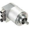
PROFINET IO
2)
± 79
(with 8192 steps)Single-turn
13 bit (8192 steps)Multi-turn
27 bit
(8192 steps ×
16384 revolutions)IP67/IP64
S/R = signals/revolution
1) Built‑on rotary encoders can be used for Safety Integrated.
2) If you require information about the usability of built‑on rotary encoders for Safety Integrated, please contact your local Siemens office.
Absolute encoders, incremental encoders and mounting accessories
The built‑on optoelectronic rotary encoders sense distances, angles of rotation or speeds in machines. They can be used in conjunction with numerical control systems, programmable logic controllers, drives and position displays, e.g. for:
- SINUMERIK CNC controls
- SIMOTION Motion Control Systems
- SIMATIC programmable logic controllers
- SINAMICS drive systems
Область применения
A distinction is made between incremental and absolute measuring procedures:
- In the case of incremental encoders, the machine must travel to a reference point after each power‑off state, as the position is not usually stored in the controller, and movements of the machine while the power is off are not recorded.
- Absolute encoders, on the other hand, also record these movements while the power is off and return the actual position with power On. Travel to a reference point is not necessary.
Дизайн
All encoders are available in Synchro flange and clamp flange versions. Encoders with a Synchro flange can be attached to the machine with 3 clamps or mounted with axial screws. The encoder is driven by means of a plug‑in coupling or a spring disk coupling. Alternatively, pulleys can also be used.
The encoder supply voltage is 5 V DC or alternatively 10 V to 30 V DC. The 10 V to 30 V DC version supports longer cable lengths. Most control systems apply the supply voltage directly at the measuring circuit connector. With SINAMICS, the power supply for the measuring systems is provided via the Sensor Modules.
For rotary encoders with cables, the cable length including the connector is 1 m (3.28 ft).
The following bending radii for the cables at the encoder must be observed:
- One‑time bending: ≥ 20 mm (0.79 in)
- Continuous bending: ≥ 75 mm (2.95 in)
Дальнейшая информация
Power supply
The measuring systems only fulfil the requirements stipulated in the standard IEC 61010-1 if the power is supplied from a secondary circuit with limited power according to IEC 61010-13rd Ed., Section 9.4 or with limited power according to IEC 60950-12nd Ed., Section 2.5, or from a secondary circuit Class 2 according to UL1310. You can also use the corresponding sections of the standards DIN EN 61010-1, EN 61010-1, UL 61010-1 and CAN/CSA-C22.2 No. 61010-1 instead of the standard IEC 61010-13rd Ed., Section 9.4, respectively the corresponding sections of the standards DIN EN 60950-1, EN 60950-1, UL 60950-1 and CAN/CSA-C22.2 No. 60950-1 instead of the standard IEC 60950-12nd Ed., Section 2.5.