
- Каталог оборудования Siemens
- Каталог продуктов Siemens Industry
- Приводная техника
- Техника автоматизации
- Системы автоматизации
- Системы визуализации SIMATIC HMI
- Системы идентификации
- Промышленные коммуникации SIMATIC NET
- Промышленные аппараты управления SIRIUS
- Промышленные информационные технологии
- Управление на базе РС
- Системы управления процессом
- Контрольно-измерительные приборы
- Анализаторы процесса
- Блоки питания SITOP
- Продукты для специальных требований
- Модули с расширенным температурным диапазоном SIPLUS
- Промышленные системы автоматизации SIMATIC
- Система управления перемещением SIMOTION
- Распределенные системы управления
- Системы оперативного управления и мониторинга
- Промышленные коммуникации
- Аппаратура управления
- Блоки питания
- Дополнения SIPLUS
- Системы телеметрии
- IO Systems for heating units
- Automatic door controls
- Condition monitoring systems
- Time synchronization
- Модули с расширенным температурным диапазоном SIPLUS
- Energy
- Автоматизация и безопасность зданий
- Низковольтная коммутационная техника
- Технология безопасности
- Системные решения и продукты для отраслей
- Сервис
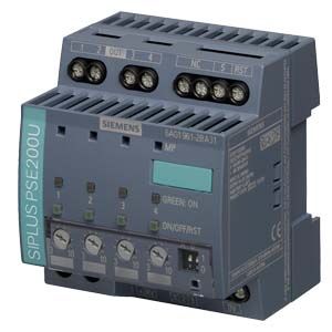
SIPLUS selectivity module
- Заказные данные (1)
- Аксессуары (1)
- Информационные материалы
Информационные материалы
Selectivity and rapid fault localization in 24 V feeders
The SITOP PSE200U and SITOP select selectivity modules are the optimal expansion for all 24 V power supplies to distribute the load current to several feeders and to monitor it. Overload and short-circuit in one or more feeders is reliably detected and signaled.
The electronics permit brief current peaks caused, for example, by high inrush currents, but disconnects feeders in the event of an extended overload. This is ensured even on high-resistance lines and in the case of "creeping" short-circuits. In such cases, miniature circuit breakers fail to trip, or trip too late, even if the power supply unit could deliver the required tripping current. The SITOP expansion module continues to supply the intact feeders with 24 V absolutely free of interruptions and feedback – a feature which avoids a possible total system failure.
Note
SIPLUS extreme products are based on Siemens standard products. The contents listed here were taken from the corresponding standard products. SIPLUS extreme-specific information was added.
Область применения
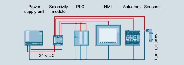
The selectivity module is used in conjunction with 24 V power supplies to distribute the load current over several feeders and to monitor the individual currents. Faults in individual circuits caused by overload or short-circuit are detected and selectively switched off so that further load current paths remain unaffected by the fault. This achieves fast fault diagnostics and minimizes downtimes.
Дизайн
The selectivity module is specially designed for the response of switched-mode power supply units and the 24 V DC feeders to be supplied. Individual setting of the current allows optimum adaptation to the respective feeder.
Функции
Monitoring
The current per output is monitored by the selectivity modules; if the set threshold of the output is exceeded, the output is switched off according to a predefined time-current characteristic curve. In addition, the supplying 24 V input voltage is constantly being monitored. As soon as this voltage threatens to fail, the path with a higher current than the set threshold is disconnected immediately. All other feeders continue to be supplied without interruption.Signaling
Signaling of the faulty feeder takes place by the LEDs on the device as well as via group signaling contact or single-channel signaling. The selectivity module with single-channel signaling outputs the status of the 4 outputs cyclically by means of a serial code which can be read in by a digital PLC input.Free function blocks for SIMATIC S7-300/400/1200/1500 for STEP 7 and TIA Portal as well as SIMOTION CPUs with SIMOTION SCOUT are available for evaluation. This enables simple integration into the S7 diagnostics and host control or HMI systems.
More information, as well as the function blocks for download, can be found at:
SIMATIC S7:
http://support.automation.siemens.com/WW/view/en/61450284SIMOTION:
http://support.automation.siemens.com/WW/view/en/82555461Connection and disconnection of the outputs
During device startup you can select between simultaneous connection of all outputs as well as sequential connection or load-dependent connection of the outputs (to reduce the peak inrush currents).Each output can be manually connected and disconnected on the device (for example, for commissioning or service). Disconnected outputs can be connected by means of remote reset (24 V input). Prerequisite is that the outputs were not disconnected manually on the device.
Особенности
- Reliable shutdown in case of overload regardless of cable lengths or cable cross-sections
- 4 load feeders per module with individually adjustable response threshold for each output
- Two versions for remote diagnostics: Group signaling contact or single-channel signaling
- Evaluation via free-of-charge SIMATIC S7 function blocks (S7-1500/1200/300/400) for modules with single-channel signaling (PSE200U)
- LEDs for rapid on-site fault localization
- Remote reset possible from a central location (PSE200U)
- Simple commissioning thanks to manual switch on/off of outputs (PSE200U)
- Sequential connection of feeders to reduce total inrush current
- Sealable transparent cover over adjusters for currents and times protects against maladjustment (PSE200U)
Технические данные
Order number
6EP1961-2BA11
6EP1961-2BA31
6EP1961-2BA51
6EP1961-2BA61
product brandname
SITOP PSE200U
SITOP PSE200U
SITOP PSE200U
SITOP PSE200U
Type of current supply
Selectivity module, 4 x 3 A Common signal contact
Selectivity module, 4 x 3 A Single-channel signaling
Selectivity module, 4 x 3 A NEC Class 2, Common signal contact
Selectivity module, 4 x 3 A NEC Class 2, Single-channel signaling
Input
Type of the power supply network
Controlled DC voltage
Controlled DC voltage
Controlled DC voltage
Controlled DC voltage
Supply voltage at DC Rated value
24 V
24 V
24 V
24 V
Input voltage at DC
22 ... 30 V
22 ... 30 V
22 ... 30 V
22 ... 30 V
Overvoltage overload capability
35 V
35 V
35 V
35 V
Input current at rated input voltage 24 V Rated value
12 A
12 A
12 A
12 A
Output
Voltage curve at output
controlled DC voltage
controlled DC voltage
controlled DC voltage
controlled DC voltage
Formula for output voltage
Vin - approx. 0.2 V
Vin - approx. 0.2 V
Vin - approx. 0.2 V
Vin - approx. 0.2 V
Relative overall tolerance of the voltage Note
In accordance with the supplying input voltage
In accordance with the supplying input voltage
In accordance with the supplying input voltage
In accordance with the supplying input voltage
Number of outputs
4
4
4
4
Output current up to 60 °C per output rated value
3 A
3 A
3 A
3 A
Adjustable pick-up value current of the current-dependent overload release
0.5 ... 3 A
0.5 ... 3 A
0.5 ... 3 A
0.5 ... 3 A
Type of response value setting
via potentiometer
via potentiometer
via potentiometer
via potentiometer
Product feature parallel switching of outputs
No
No
No
No
Product feature bridging of equipments
Yes
Yes
Yes
Yes
Type of outputs connection
Simultaneous connection of all outputs after power up of the supply voltage > 20 V, delay time of 25 ms, 100 ms or adjustable "load optimised" via DIP switch for sequential connection
Simultaneous connection of all outputs after power up of the supply voltage > 20 V, delay time of 25 ms, 100 ms or adjustable "load optimised" via DIP switch for sequential connection
Simultaneous connection of all outputs after power up of the supply voltage > 20 V, delay time of 25 ms, 100 ms or adjustable "load optimised" via DIP switch for sequential connection
Simultaneous connection of all outputs after power up of the supply voltage > 20 V, delay time of 25 ms, 100 ms or adjustable "load optimised" via DIP switch for sequential connection
Efficiency
Efficiency in percent
97 %
97 %
97 %
97 %
Power loss [W] at rated output current at rated output current typical
9 W
9 W
9 W
9 W
Switch-off characteristic per output
Switching characteristic
● of the excess current
Iout = 1.0 ...1.5 x set value, switch-off after approx. 5 s
Iout = 1.0 ...1.5 x set value, switch-off after approx. 5 s
Iout = 1.0 ...1.1 x set value, switch-off after approx. 5 s
Iout = 1.0 ...1.1 x set value, switch-off after approx. 5 s
● of the current limitation
Iout = 1.5 x set value, switch-off after typ. 100 ms
Iout = 1.5 x set value, switch-off after typ. 100 ms
Iout = 1.1 x set value, switch-off after typ. 100 ms
Iout = 1.1 x set value, switch-off after typ. 100 ms
● of the immediate switch-off
Iout > set value and Vin < 20 V, switch-off after approx. 0.5 ms
Iout > set value and Vin < 20 V, switch-off after approx. 0.5 ms
Iout > set value and Vin < 20 V, switch-off after approx. 0.5 ms
Iout > set value and Vin < 20 V, switch-off after approx. 0.5 ms
Design of the reset device/resetting mechanism
via sensor per output
via sensor per output
via sensor per output
via sensor per output
Remote reset function
Non-electrically isolated 24 V input (signal level "high" at > 15 V)
Non-electrically isolated 24 V input (signal level "high" at > 15 V)
Protection and monitoring
Overload protection type for cables
5 A per output (not accessible)
5 A per output (not accessible)
5 A per output (not accessible)
5 A per output (not accessible)
Display version for normal operation
Three-color LED per output: green LED for "Output switched through"; yellow LED for "Output switched off manually"; red LED for "Output switched off due to overcurrent"
Three-color LED per output: green LED for "Output switched through"; yellow LED for "Output switched off manually"; red LED for "Output switched off due to overcurrent"
Three-color LED per output: green LED for "Output switched through"; yellow LED for "Output switched off manually"; red LED for "Output switched off due to overcurrent"
Three-color LED per output: green LED for "Output switched through"; yellow LED for "Output switched off manually"; red LED for "Output switched off due to overcurrent"
Design of the switching contact for signaling function
Common signal contact (changeover contact, rating 0.1 A/24 V DC)
Status signal output (pulse/pause signal, can be evaluated via Simatic function block)
Common signal contact (changeover contact, rating 0.1 A/24 V DC)
Status signal output (pulse/pause signal, can be evaluated via Simatic function block)
Safety
Galvanic isolation between input and output at switch-off
No
No
No
No
Operating resource protection class
Class III
Class III
Class III
Class III
Certificate of suitability
● CE marking
Yes
Yes
Yes
Yes
● as approval for USA
UL-Recognized (UL 2367) File E328600; cULus-Listed (UL 508, CSA C22.2 No. 107.1) File E197259
UL-Recognized (UL 2367) File E328600; cULus-Listed (UL 508, CSA C22.2 No. 107.1) File E197259
UL-Recognized (UL 2367) File E328600
UL-Recognized (UL 2367) File E328600
Standard for safety
according to EN 60950-1 and EN 50178
according to EN 60950-1 and EN 50178
according to EN 60950-1 and EN 50178
according to EN 60950-1 and EN 50178
Certificate of suitability relating to ATEX
IECEx Ex nA nC IIC T4 Gc; ATEX (EX) II 3G Ex nA nC IIC T4 Gc; cCSAus Class I, Div. 2, Group ABCD, T4
IECEx Ex nA IIC T4 Gc; ATEX (EX) II 3G Ex nA IIC T4 Gc; cCSAus Class I, Div. 2, Group ABCD, T4
IECEx Ex nA nC IIC T4 Gc; ATEX (EX) II 3G Ex nA nC IIC T4 Gc
IECEx Ex nA IIC T4 Gc; ATEX (EX) II 3G Ex nA IIC T4 Gc
Shipbuilding approval
GL, ABS
GL, ABS
GL and ABS in process
GL and ABS in process
Protection class IP
IP20
IP20
IP20
IP20
EMC
Standard
● for emitted interference
EN 55022 Class B
EN 55022 Class B
EN 55022 Class B
EN 55022 Class B
● for interference immunity
EN 61000-6-2
EN 61000-6-2
EN 61000-6-2
EN 61000-6-2
Operating data
Ambient temperature
● during operation
0 ... 60 °C
0 ... 60 °C
0 ... 60 °C
0 ... 60 °C
— Note
with natural convection
with natural convection
with natural convection
with natural convection
● during transport
-40 ... +85 °C
-40 ... +85 °C
-40 ... +85 °C
-40 ... +85 °C
● during storage
-40 ... +85 °C
-40 ... +85 °C
-40 ... +85 °C
-40 ... +85 °C
Environmental category acc. to IEC 60721
Climate class 3K3, no condensation
Climate class 3K3, no condensation
Climate class 3K3, no condensation
Climate class 3K3, no condensation
Mechanics
Type of electrical connection
screw-type terminals
screw-type terminals
screw-type terminals
screw-type terminals
● at input
+24 V: 2 screw terminals for 0.5 ... 10 mm²; 0 V: 2 screw terminals for 0.5 ... 4 mm²
+24 V: 2 screw terminals for 0.5 ... 10 mm²; 0 V: 2 screw terminals for 0.5 ... 4 mm²
+24 V: 2 screw terminals for 0.5 ... 10 mm²; 0 V: 2 screw terminals for 0.5 ... 4 mm²
+24 V: 2 screw terminals for 0.5 ... 10 mm²; 0 V: 2 screw terminals for 0.5 ... 4 mm²
● at output
Output 1 ... 4: 1 screw terminal each for 0.5 ... 4 mm²
Output 1 ... 4: 1 screw terminal each for 0.5 ... 4 mm²
Output 1 ... 4: 1 screw terminal each for 0.5 ... 4 mm²
Output 1 ... 4: 1 screw terminal each for 0.5 ... 4 mm²
● for signaling contact
3 screw terminals for 0.5 ... 4 mm²
1 screw terminal for 0.5 ... 4 mm²
3 screw terminals for 0.5 ... 4 mm²
1 screw terminal for 0.5 ... 4 mm²
● for auxiliary contacts
Remote reset: 1 screw terminal for 0.5 ... 4 mm²
Remote reset: 1 screw terminal for 0.5 ... 4 mm²
Remote reset: 1 screw terminal for 0.5 ... 4 mm²
Remote reset: 1 screw terminal for 0.5 ... 4 mm²
Width of the enclosure
72 mm
72 mm
72 mm
72 mm
Height of the enclosure
80 mm
80 mm
80 mm
80 mm
Depth of the enclosure
72 mm
72 mm
72 mm
72 mm
Installation width
72 mm
72 mm
72 mm
72 mm
Mounting height
180 mm
180 mm
180 mm
180 mm
Net weight
0.2 kg
0.2 kg
0.2 kg
0.2 kg
Mounting type
Snaps onto DIN rail EN 60715 35x7.5/15
Snaps onto DIN rail EN 60715 35x7.5/15
Snaps onto DIN rail EN 60715 35x7.5/15
Snaps onto DIN rail EN 60715 35x7.5/15
Mechanical accessories
Device identification label 20 mm × 7 mm, pale turquoise 3RT1900-1SB20
Device identification label 20 mm × 7 mm, pale turquoise 3RT1900-1SB20
Device identification label 20 mm × 7 mm, pale turquoise 3RT1900-1SB20
Device identification label 20 mm × 7 mm, pale turquoise 3RT1900-1SB20
MTBF at 40 °C
755 915 h
755 915 h
755 915 h
755 915 h
Other information
Specifications at rated input voltage and ambient temperature +25 °C (unless otherwise specified)
Specifications at rated input voltage and ambient temperature +25 °C (unless otherwise specified)
Specifications at rated input voltage and ambient temperature +25 °C (unless otherwise specified)
Specifications at rated input voltage and ambient temperature +25 °C (unless otherwise specified)