
- Каталог оборудования Siemens
- Каталог продуктов Siemens Industry
- Приводная техника
- Техника автоматизации
- Системы автоматизации
- Системы визуализации SIMATIC HMI
- Системы идентификации
- Промышленные коммуникации SIMATIC NET
- Промышленные аппараты управления SIRIUS
- Промышленные информационные технологии
- Управление на базе РС
- Системы управления процессом
- Система управления процессом SIMATIC PCS 7
- Системные компоненты
- Носитель данных и логистика
- Системное администрирование
- Базовые платформы для ES/OS/BATCH/IT
- Проектирование
- Операторские станции
- OS долговременное архивирование
- Контроль оборудования
- Системы автоматизации
- SIMATIC PCS 7 BOX
- Средства коммуникации
- Устройства ввода/вывода
- Рецептурные процессы
- SIMATIC Route Control
- Интеграция средств безопасности в автоматизацию процессов
- IT Безопасность
- Технологические компоненты
- Симуляторы и системы тренинга
- Пакеты обновлений
- Add-Ons для SIMATIC PCS 7
- Заказные номера предыдущей версии SIMATIC PCS 7 V6.1
- Системные компоненты
- Система управления процессом SIMATIC PCS 7
- Контрольно-измерительные приборы
- Анализаторы процесса
- Блоки питания SITOP
- Продукты для специальных требований
- Energy
- Автоматизация и безопасность зданий
- Низковольтная коммутационная техника
- Технология безопасности
- Системные решения и продукты для отраслей
- Сервис

SIMATIC PCS 7 Logic Matrix
- Заказные данные (1)
- Информационные материалы
Информационные материалы

Logic Matrix Editor within the SIMATIC PCS 7 Engineering System
The SIMATIC PCS 7 Logic Matrix is based on the principle of logic creation with a cause and effect matrix - similar to the SIMATIC Safety Matrix for safety-related applications that has been established for years. It enables easy creation of the interlock logic between technological functions (e.g. control modules or equipment modules) of the automation project. There is no time-consuming configuring of the interlock logic in the CFC.
The SIMATIC PCS 7 Logic Matrix Tool, which can be opened from SIMATIC Manager, is used to create and edit the Logic Matrix oriented to one controller in each case and then to integrate the created matrix data at the chart level in the CFC project. The APL-based process tag types of the Control Module are linked with the cause or effect blocks of the Logic Matrix by templates created with the Link Type Editor of the Logic Matrix (Link Types).
The matrix table is comparable to a spreadsheet program. The configuration engineer first enters the possible events (inputs) in the horizontal lines, and then configures their type and number, logic operations, timings, alarms and possible bypass functions. He then defines possible actions (outputs) to these events in the vertical columns. The events and reactions are linked by simply clicking the cell at the intersection of the row and column.
The SIMATIC PCS 7 Safety Matrix Viewer enables operator control and monitoring of the Logic Matrix on the operator station (OS Single Station and OS Client). The Logic Matrix faceplate can also be opened via the faceplates of the technology objects which have been linked together via the cause and effect matrix.
Based on this causal chain, jumps from the Effect faceplate to the Cause faceplate and vice versa are possible via the Logic Matrix faceplate.
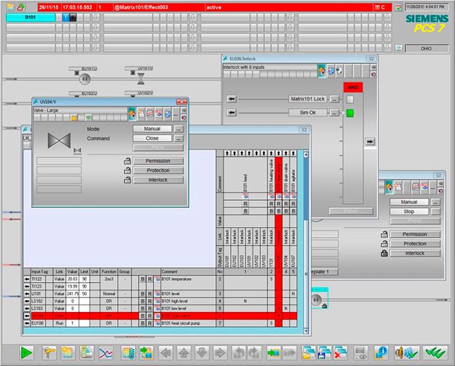
Faceplates of the Logic Matrix and the linked Control Module in the Logic Matrix Viewer of the SIMATIC PCS 7 Operator Station